Duct Bank Properties
The Duct Bank Property Manager contains many of the options which were originally defined in the Duct Bank Router when the selected duct bank component were placed. While the conduit types and sizes cannot be changed, properties related to the conduit can be modified.
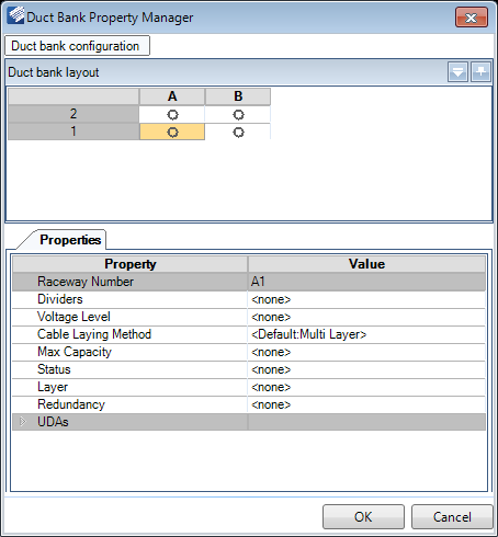
Click this option, then select the duct bank component in the drawing to display the following dialog.
When you click on a cell in the Duct bank layout, the defined values for the conduit in that cell are displayed in the Property fields. These can be modified and saved.
Once you have finished making changes to any of the fields in this dialog, click OK to apply them and close the dialog or click Cancel to close the dialog without saving the changes.
Duct Bank configuration
Click the Duct Bank configuration icon at the top of the dialog to display the following drop down with options to define the Configuration and Cable system:

| Setting | Description |
|---|---|
| Configuration | The Configuration field will list saved configurations if any exist, which can be loaded and used/modified. It also allows you to type in the name for a new configuration and save it for future use. |
| Cable System | The Cable system field lists the active system as defined in the System field in the Properties section of the Routing Tool. When routing duct bank, Conduits are the only Cable System that will apply. |
| Setup Spacers Configuration | Spacers are used in the duct bank to define the size and distance between conduit in the duct bank being routed. Click the icon to display the Spacer Configuration Tool allowing you to define the layout and properties for the spacers. |
| Set Conduit Layout Only | Display the Setup Grid dialog allowing you to define the number of conduit slots to include in the duct bank. |
| Save | Saves the current configuration setup. |
| Preview | Displays a preview of duct bank arrangement as shown below: |
Duct Bank Layout
The Duct Bank Layout section display the Duct Bank configuration as it was defined in the section above and allows you to define the Property/Preference values for the conduit which will be run through the duct bank.
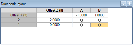
Click in a grid cell and use the Properties section to define the conduit properties. Each cell can contain different size conduit components with unique property values. You can also copy a component from one cell and paste it into others, which will copy the property values as well.
The Offset values define the spacing between the conduit components and the value is typed directly into the field.
Duct Bank Properties
| Setting | Description |
|---|---|
| Raceway Number | This number corresponds with the column and row of the Ductband layout. For example Column A, Row 1 would have a Raceway Number of A1. |
| Dividers | If the raceway is to be divided into different sections, define a number of dividers to use here. |
| Voltage Level | Select a voltage level from the drop down list: |
| Cable Laying Method | Select the method of laying the cable from the following list of options. This determines the routing configuration for the cable inside the raceway/conduit. |
| Max Capacity | The Max Capacity determines the maximum percentage of the raceway/conduit which can be occupied by cables. |
| Status | Define the status for the duct bank from the following list: |
| Layer | Select which layer the duct bank will be modeled on from the drop down list. By default, duct bank is placed on a specific layer as defined in the CAD Standards > Levels page of the Options dialog. |
| Redundancy | This field will assign a label to redundancy runs
which may be required. The default labels to select from are:
Additional label values can be defined in the Raceway > Specifications page of the Options dialog. |
| UDAs | Lists User Defined Attributes such defined for the duct bank. |